All American Picket Gate
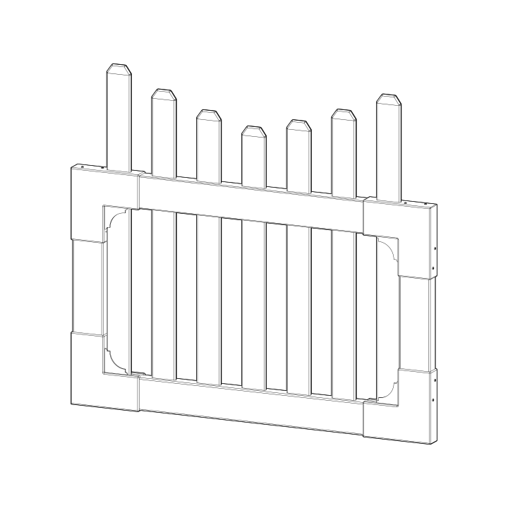
Before You Begin
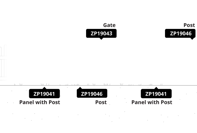
- Read your All American Fence (ZP19041) install guide first — your gate and fence work better together when you understand how the fence goes in.
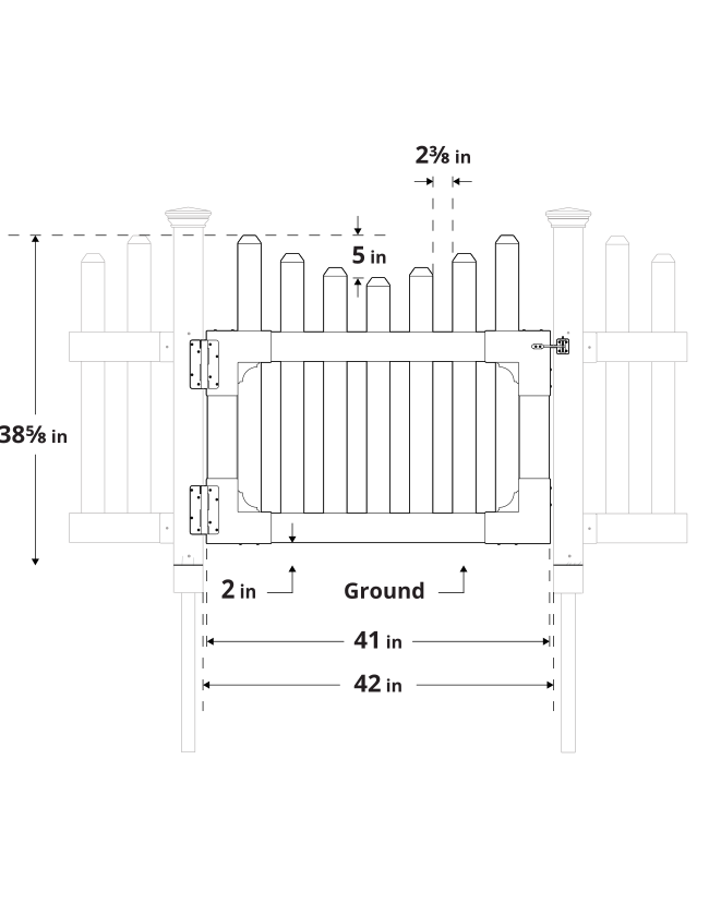
- Dry-fit the gate frame before you drive a single screw. A dry run confirms every piece is in the box, that you have the assembly order right, that everything fits and functions, and that your gate matches the measurements shown in the specifications below. Troubleshooting is far easier before anything is screwed together — take the frame back apart as needed, then reassemble it permanently with the 1¼" self-drilling stainless steel screws.
- Position and install your gate posts before your fence posts. Fence panels are more forgiving of a custom fit than a gate is.
- Call 811 before you pound pipes to check for underground utilities — this gate needs two finishing posts set into the ground.
Returns: Please let us help resolve any issues before initiating a return. If a return is still necessary, it must be initiated with the retailer where the product was purchased.
Need Help or Replacement Parts?
Our US-based customer service team is available Monday-Friday, 9am-5pm EST.
- Parts Website: https://parts.nychbrands.com
- Email: hmmm@wambamfence.com
- Phone: 704-892-5222 or 877-778-5733
For faster service, have your item number (ZP19043) and part name ready. Your original product box is also helpful if available.
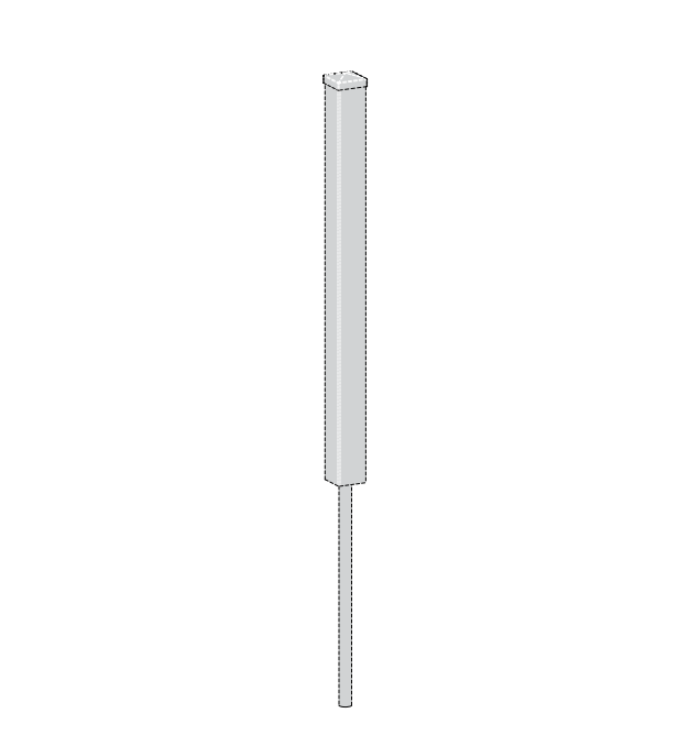
Finishing Post: ZP19046
Gates do not come with their own posts
You will need two Finishing Posts — one to finish the fence run, and one to support the gate.
Buying Guide
Product Specifications & Dimensions
Required Tools
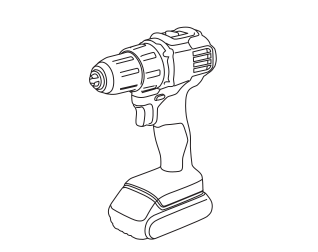
Drill (with 2" bit)
Measuring Tape
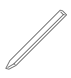
Pencil
Stringline Reel
Stakes (for stringline)
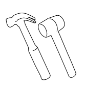
Hammer or Mallet (Optional for stakes)
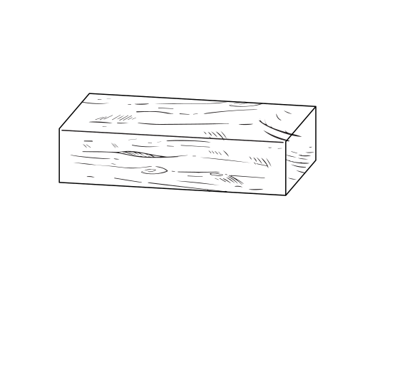
Wood Block
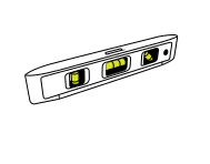
1 ft Level
Part Identification
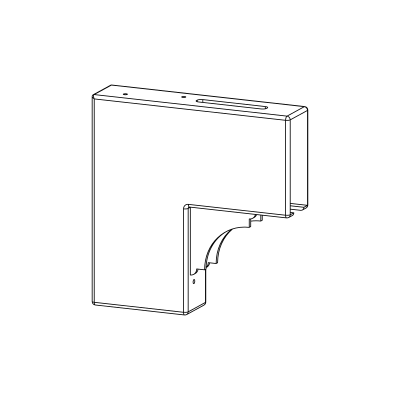
A
Top Gate Bracket (2)
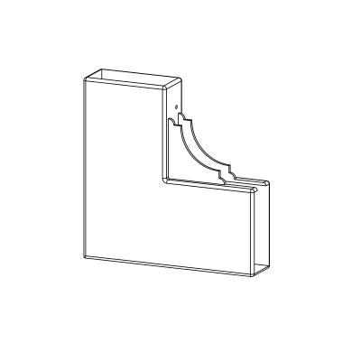
B
Bottom Gate Bracket (2)
C
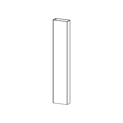
Vertical Stile (2)
1½" x 3½" x 18⅛"
D
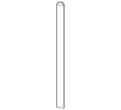
Picket (7)
See below for specific measurements
E
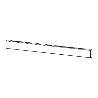
Top Rail (1)
1½" x 3½" x 40¾"
F
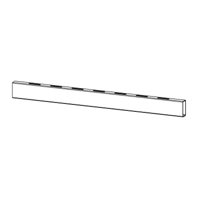
Bottom Rail (1)
1½" x 3½" x 40¾"
Note: Pickets (D) are graduated in height — the number on the bottom of each picket corresponds to the dimensions below.
#1 (2) - ⅜" x 2¾" x 36½" | #2 (2) - ⅜" x 2¾" x 34⅜" | #3 (2) - ⅜" x 2¾" x 32¾" | #4 (1) - ⅜" x 2¾" x 31½"
G
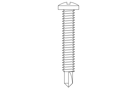
1¼" White Self-Drilling Stainless Steel Screw (24)
H
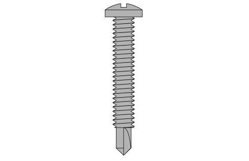
1¼" Black Self-Drilling Stainless Steel Screw (38)
I
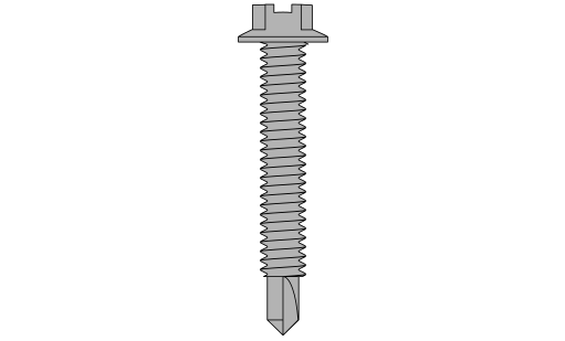
1¼" Black Self-Drilling Hex Head Steel Screw (4)
J
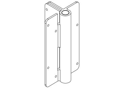
Hinge (2)
K
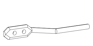
Latch Finger (1)
L
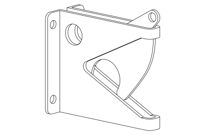
Latch Catch (1)
Hinge Post Support
Do not hang your gate off a single unsupported post. Your gate will perform better and last longer if the hinge post is connected to a panel of fence that is connected to another post — that way the weight strain is carried by two posts instead of one. Installing fence panels on both sides of your gate is ideal in all situations. If space restrictions make this impossible, contact us for alternative solutions.
Step 1: Bottom Rail Assembly
Parts Required
B x2 F x1
Insert the Bottom Rail (F) fully into the first Bottom Gate Bracket (B), then insert the opposite end into the second bracket. Push each end all the way to the seating point shown.
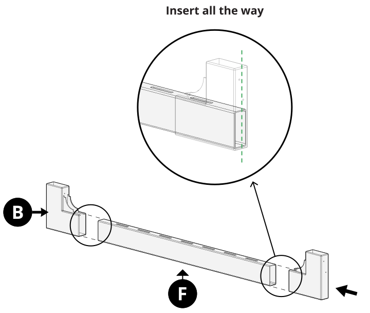
Note: The bottom rail does not have any picket holes on the bottom — use the holes to confirm you have it right side up.
Step 2: Vertical Stiles
Parts Required
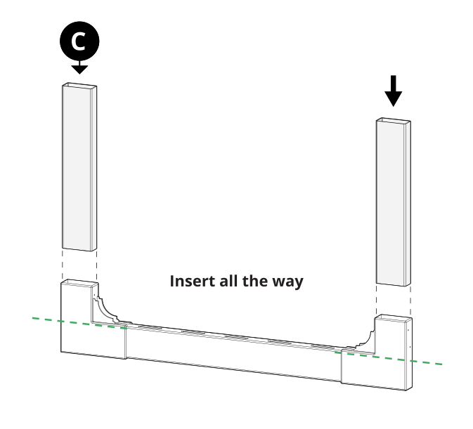
C x2
Insert both Vertical Stiles (C) into the Bottom Gate Brackets (B). They will bottom out against the bottom rail.
Step 3: Top Rail Assembly
Parts Required
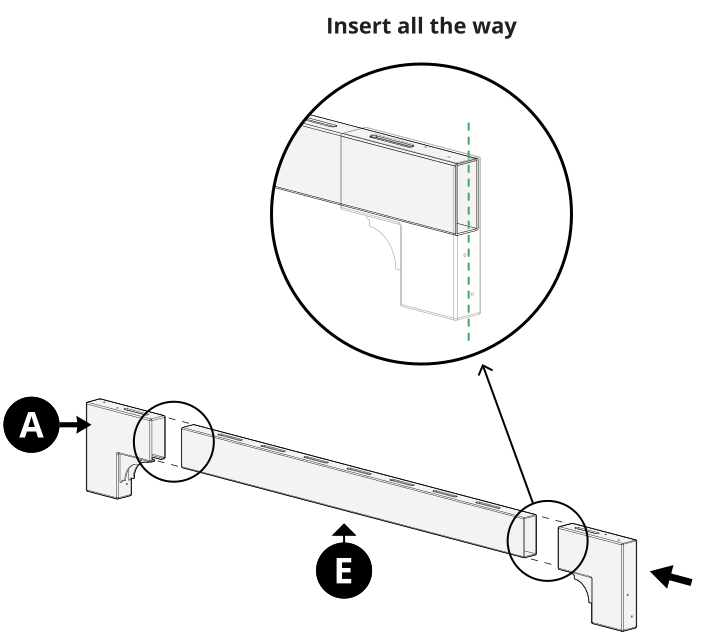
A x2 E x1
Insert the Top Rail (E) fully into the first Top Gate Bracket (A), then insert the opposite end into the second bracket. Push each end all the way to the seating point shown.
Step 4: Frame Assembly
Slide the assembled top — top gate brackets and top rail together — down over the vertical stiles, applying pressure to all four corners to keep a tight fit.
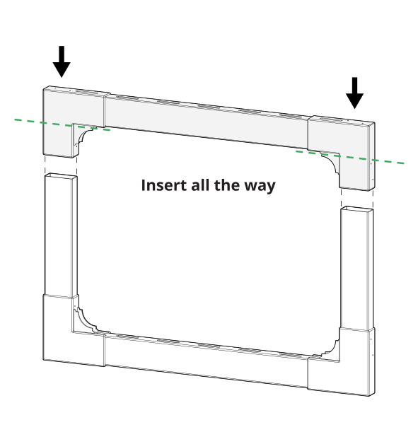
Step 5: Fasten the Frame
Parts Required
G x20
Fasten the gate brackets to the frame with 20 of the 1¼" White Self-Drilling Stainless Steel Screws (G). Apply pressure at the corners as you drive the screws to keep the frame square.
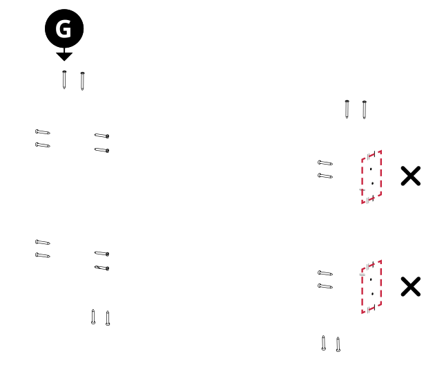
Note: Do not install the outward-facing screws on one side — that side needs to stay clear for hinge installation.
Step 6: Insert Pickets
Parts Required
D x7
Insert the Pickets (D) through the top rail and down into the bottom rail, in the pattern indicated. Don't be afraid to use muscle — you won't break the vinyl.
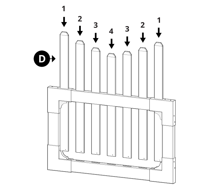
Note: Pickets are graduated in height — insert them in the pattern shown, from the outside in: 1, 2, 3, 4, 3, 2, 1.
Step 7: Fasten Hinges to Gate
Parts Required
J x2 H x8
Fasten the Hinges (J) onto the gate brackets with 8 of the 1¼" Black Self-Drilling Stainless Steel Screws (H).
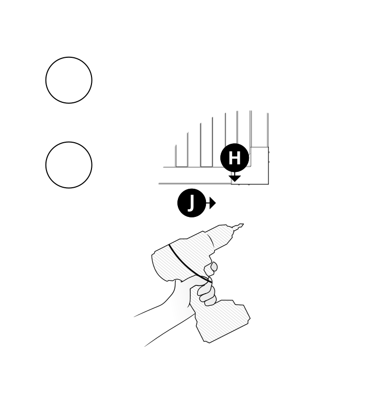
Step 8: Support the Gate
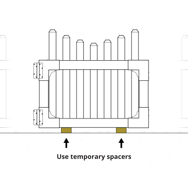
Rest the gate on temporary spacers or wood blocks to hold it at the right height while you hang it. This keeps the gate level and takes the weight off your hands and the hinges while you drive screws.
Step 9: Fasten Hinges to Post
Parts Required
H x8
Fasten the Hinges to the post with 8 of the 1¼" Black Self-Drilling Stainless Steel Screws (H).
Step 10: Secure Hinges from the Inside
Parts Required
H x16
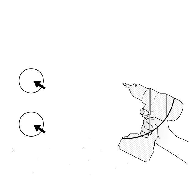
Open the gate and fasten the hinges to the post from the inside with 16 of the 1¼" Black Self-Drilling Stainless Steel Screws (H).
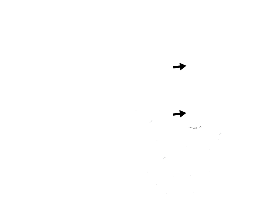
Note: If your internal pipe anchor sits close to the inside corner of the post, angle your screws to avoid it. If the pipe anchor can't be avoided, pre-drill through it and install the gate with the 1¼" Black Self-Drilling Hex Head Steel Screws (I). Do not attempt to drive the pan head screws into the pipe anchor.
Step 11: Install Latch
Parts Required
K x1 L x1 H x6
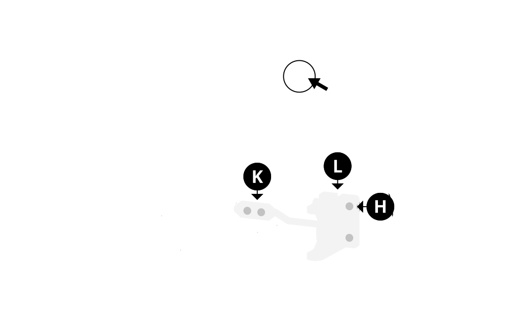
Align and fasten the Latch Catch (L) to fit and function with the Latch Finger (K), using the 6 remaining 1¼" Black Self-Drilling Stainless Steel Screws (H). Check that the gate closes and latches cleanly before driving the final screws.
Need Help?
- Email: hmmm@wambamfence.com
- Phone: 704-892-5222 or 877-778-5733
- Text: 980-580-6580
